Designing a Single-phase Liquid Immersion Cooling System
- Component Selection
- SLIC Architectures
- SLIC Tech Solutions for Immersion
- Heat Rejection Devices
- SLIC System Example Photos
- SLIC Videos
Single-phase, Liquid Immersion Cooling System Component Selection
Materials that work and what to avoid
Fluid Volume per Min per KW
Plan to circulate the Dielectric Coolant at a flow rate of roughly 2 – 4L/min per 1000W.
The calculated optimum flow rate for BC-888 is 1.2L/min per 1000W, however because no tank is perfectly efficient you should always leave at least 50% margin for larger miners and tank flow constraints.
This rate of circulation should provide plenty of safety margin to consider varying tank designs, overall volume, and ambient operating temperatures. You can fine tune the flow rate and dry cooler fan speeds based on your systems actual performance measurements.
Fluid Circulation in Tank and Dry Coolers
Your tank should be designed with the coolant being injected into bottom of the tank and removed from the top. This allows for natural convection of the coolant to assist in the fluid flow.
If you are using a non-sealed tank and a Single Loop SLIC Configuration you must ensure the coolant level in the dry cooler never exceeds the height of the coolant in the tank. If the level of the coolant in the dry cooler exceeds the level in the tank you are at risk of the coolant in the dry cooler flooding back into the tank should a vacuum break occur in the dry cooler.
Keep in mind that Centrifugal pumps are not sealed and will allow coolant to flow through them in either direction in an uncontrolled manner when they are not operating.
Heat Rejection Sizing Calculation
WM = Power use per Miner in Watts
WPS = Power use per Power Supply Watts
QM = Quantity of Miners in Tank
QPS = Quantity of Power Supplies in Tank
XSafetyFactor = A percentage of 15-25% to provide a safety factor for flow and dry cooler sizing.
(WM x QM) + (WPS x QPS) = WTOTAL (Total Watts of Heat to be Dissipated in the Tank)
WTOTAL x 100%+20%SafetyFactor / 1000W = KWDryCooler (KW size of Dry Cooler)
Pump Selection for SLIC
For circulating our Dielectric Coolants through a cooling system, we recommend the use of an appropriately sized centrifugal pump with Viton® seals (also called FKM). The pump motor should be sized so that the desired flow rate and head is well within the efficiency curve of the pump/motor combination. Explosion-proof equipment is not required.
The systems that offer the most control and variety tend to be made for hydronic heating and in-floor hydronic systems. Many manufactures offer pumps together with control systems that will monitor and maintain a temperature range as well as provide backup controls as well.
Here are a few of manufactures that we have had success with:
Grundfos Pumps – We often use CR line of inline pumps, very simple, price competitive and efficient
March Pumps – They make a wide variety of small to large pumps
View the March Pump Series MDX Products Here
Hayward / Webster – Maker of excellent small and medium pumps
View R-Series Hayward Pumps Here
View C-Series Hayward Pumps Here
Bell and Gosset – They offer a massive line-up of pumps of all sizes
FOUND A GREAT PUMP? Let us know at sales@engineeredfluids.com, and we’ll add it to the list!

You can consider any centrifugal pump with Viton (FKM) seals for your system. If you are going to use a pump made out of a resin or plastic material just make sure to check the Materials Compatibility Guide for the product you are considering and be sure to check out the materials used for the seals, impeller, and the pump chamber itself as most pumps will use a mix of materials in construction. Our coolants also provide lubrication so ceramic and carbon fiber bearings are fully compatible.
Many smaller 12v and 24v pumps used for biodiesel and fuel oil will also work well with our Coolants.
Click here to view the Grundfos Pump Sizing Tool
Click here to view the Bell and Gosset pump sizing tool
When using any pump sizing tool, make sure to pay close attention to fluid characteristics that the tool is set for as most use water as the base fluid. You can use water to get a close approximation, however, our Coolants have a higher viscosity which can result in the pump operating above its optimal efficiency range.
Selecting Pipe and Hoses for SLIC
When selecting rigid pipe for use with our coolants, its straight forward:
- Schedule 40 and Schedule 80 Chlorinated PVC (cPVC) are the best piping to use given the temperatures and pressures, we use this all the time in all our builds. You must de-rate the pipe’s maximum pressure by 30% at 50C. View PVC Sch 80 Pipe Dimenstions Here.
- Iron, Steel, Stainless, Copper, and Aluminum pipe are all fully compatible.
For flexible hose you are looking for hoses that are generally compatible with bio-diesel fuels, diesel fuel, and hydraulic fluids. Here are some good sources for hoses that are compatible with our coolants:
We use this tubing in most of our large-scale builds: Series OV200X100, Oil Vac™ – Heavy Duty Oil Resistant Polyurethane Suction Hose
VITON (FKM) hoses are great for smaller systems. Watch their pressure rating: Click Here For Extruded Tubing Pressure Rating & Click Here For Regular Viton Tubing Pressure Rating
Small Diameter Hoses for SLIC
We regularly use Tygon Versilon A-210 tubing on all our test rigs in our lab.
Another great product for hose connections of up to 1”/25mm I.D. diameter are the Parker Push-Lok Plus hoses.
These are hydraulic hoses and they come in a range sizes (1/4”/6.3mm to 1”/25mm) and colors (red, blue, black, green, gray, yellow).
What is great about this product is that the connectors are field installable without tools! You can literally just press in the barbed fittings that are designed for this product into the hose and they are ready to go, no need for a crimping machine or trip to the shop.
We recommend Parker Push-lok Plus Multipurpose Hose Model 801
- For the connectors you must use either:
What about Filters…
Filters are big question with many of our customers, since most systems are open tanks they can be susceptible to dust and dirt incursion. However, if you keep your mine clean that can eliminate a lot of the problem.
The biggest problem that most mines have with dust is their use of open vents for cooling air, this allows dirt, dust and pollution into your mine. So with the use of SLIC you should be able to eliminate entirely the source of dust as you no longer need the open vents for cooling.
That said there is always the possibility of dust in the air, but you also need to consider the impact that installing a filter will have on your system and then choosing the right approach.
- In small tanks we advise skipping a dedicated filter and once a year simply reroute the input hose system through a funnel filled with a couple of layers of paper towels they are good down to 20-30 microns. Keep in mind you need to shut down your miners or they will overheat!
For large systems we recommend installation of a bypass filter. This would be a 30 micron screw on diesel oil filter in which only a small amount (1-3%) of the total flow is actually filtered this eliminates the back pressure on the system and therefore reduces the size of the pumps needed and increases the efficiency of the system overall.
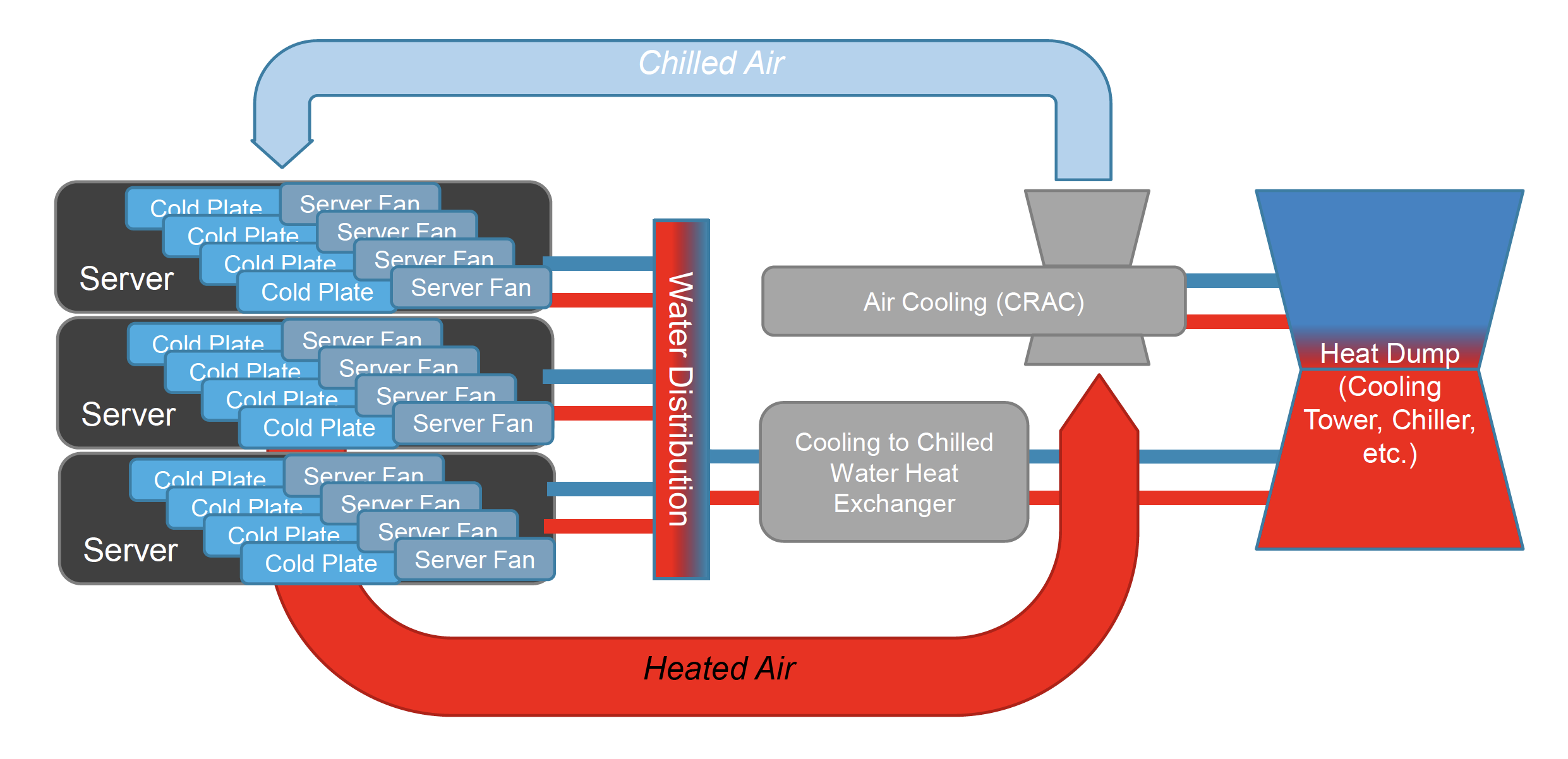
Air-Cooled vs Liquid Immersion Cooling

Typical Air-Cooled Cooling Infrastructure
Effective Cooling Range is 5kW – 25kW per Rack
Typical PUE is 1.5 – 2.3
Typical Liquid Immersion Cooling Infrastructure
Effective Cooling Range is 10kW – 200kW per Rack
Typical PUE is 1.03 – 1.07
What goes away…
- No Cold Plates
- No Server Fans
- No high-pressure water in Data Room
- No CRAC units
- No Air Handlers
- No Air Ducts
What is required…
- Immersion Container
- Coolant Distribution
- Coolant Pumps
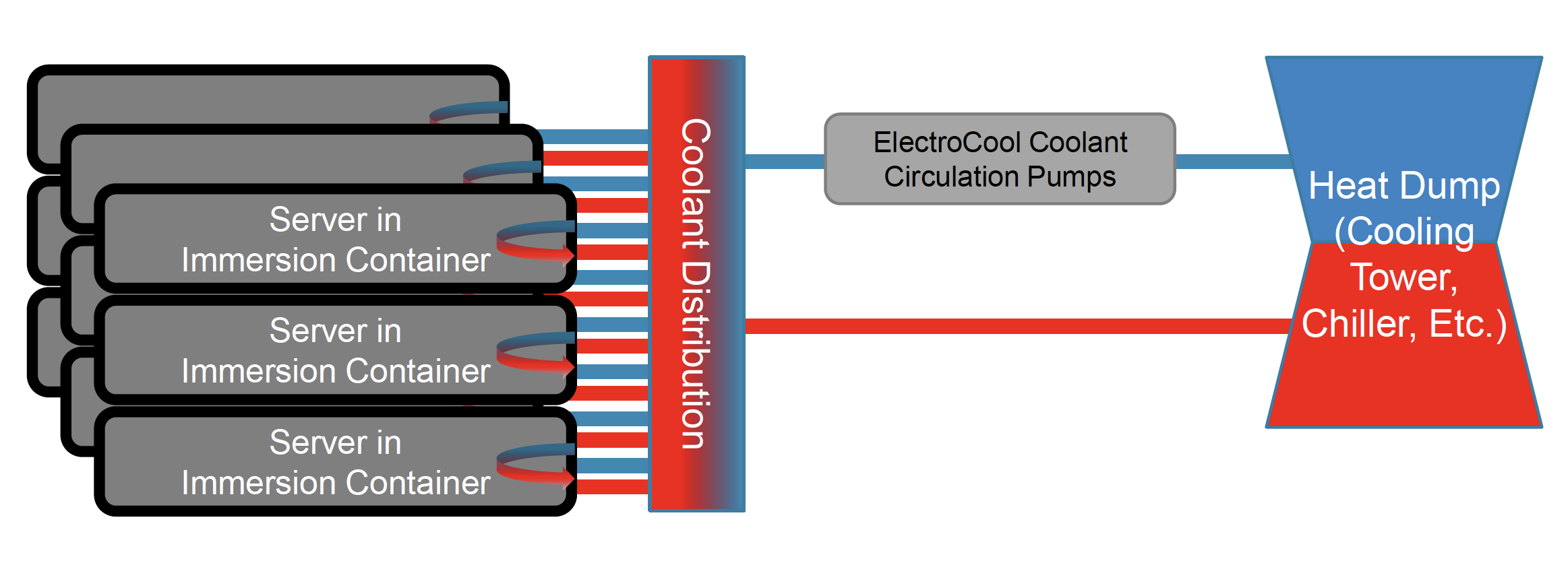
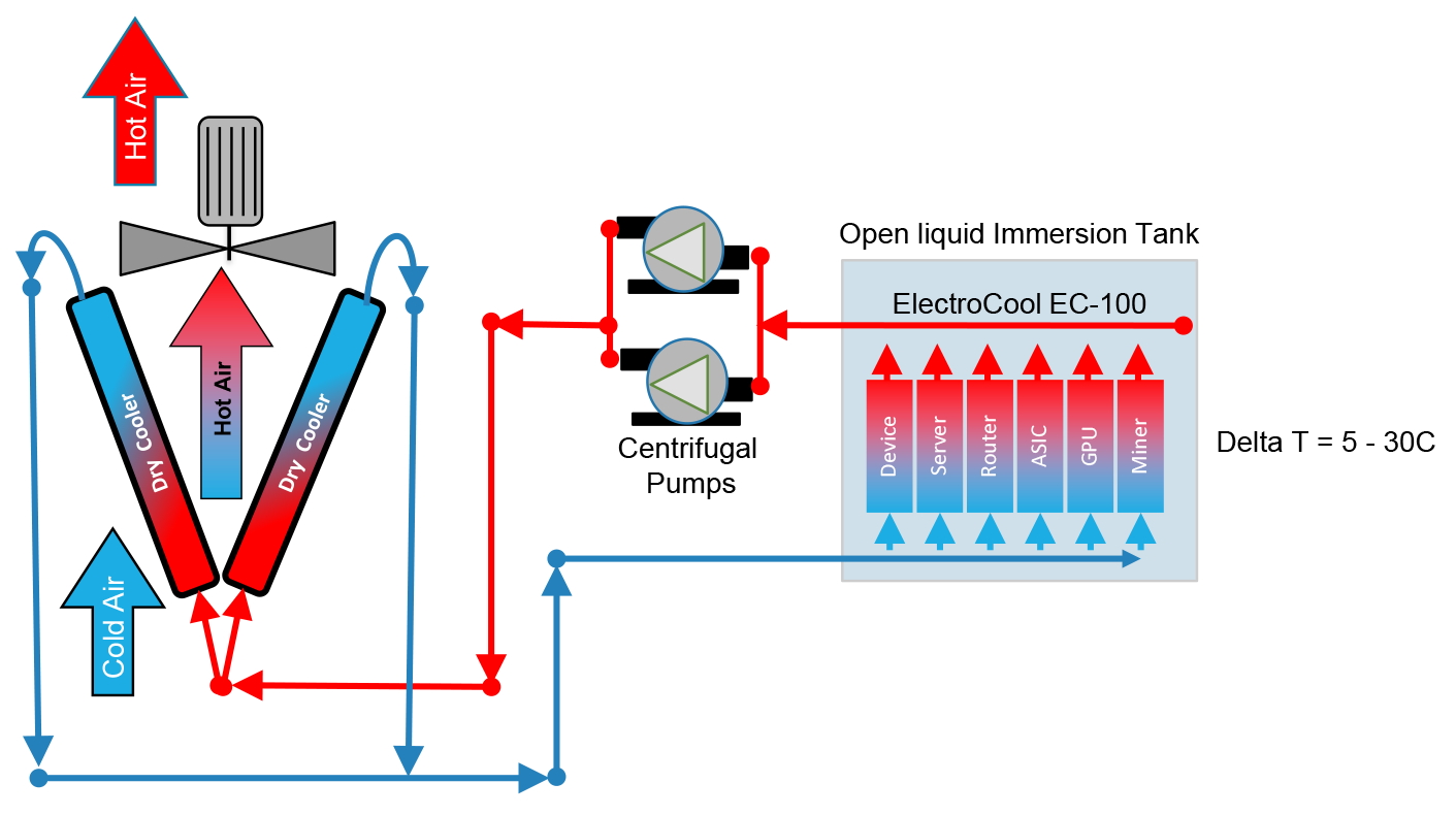
Single Loop SLIC Configuration
- The basic open tank configuration is composed of a tank in which the cold coolant is pumped into the bottom of the tank and as it flows up through the miners it absorbs the heat generated by the miners.
- Once the heated fluid reaches the top of the tank it is recovered pumped through to the dry coolers.
- Depending on the duty level of the dry cooler design a fan assists in moving cool ambient air through the liquid to air heat exchanger (radiators)
- Redundant pumps are used to circulate the fluid. Because the Dry Coolers require pressure to operate it is typically best to have the fluid pumps on the heat recovery side to provide the operating pressure and flow rate back to the tank.
- In this configuration ElectroCool Dielectric Coolant is flowing through the entire coolant loop because the dry coolers are kept at the same height as the tank. This prevents the static head of the coolant to flow everything in the tank.
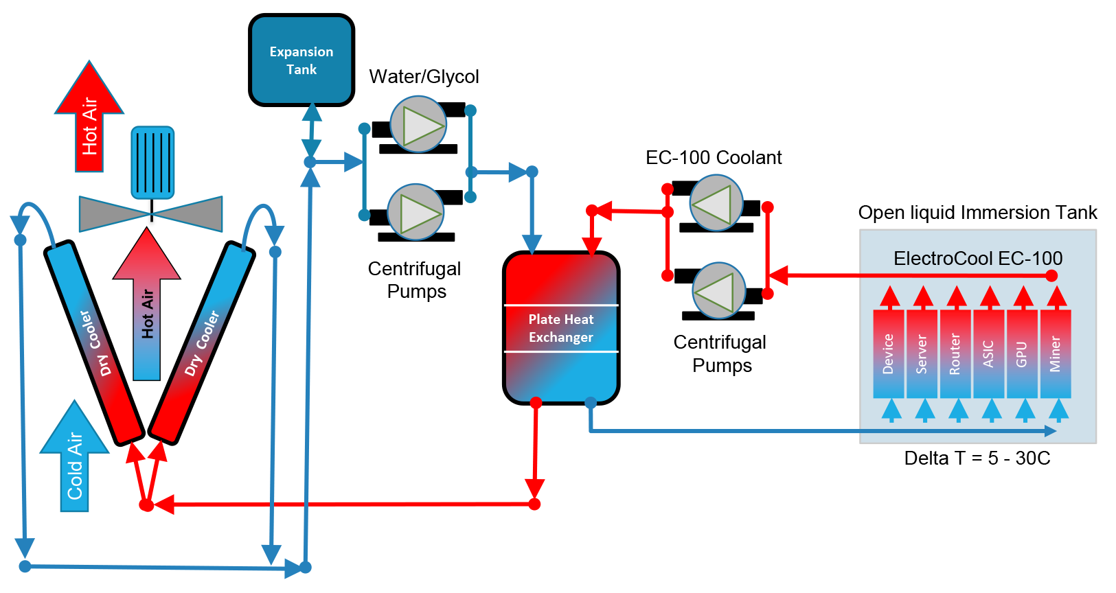
Double Loop SLIC Configuration
- In this configuration there are two loops.
- One is a coolant loop from the tank to the plate heat exchanger.
- And one water/glycol mix loop from the heat exchanger to the dry coolers.
- This configuration is used where there is a large vertical distance between the tank and the dry coolers.
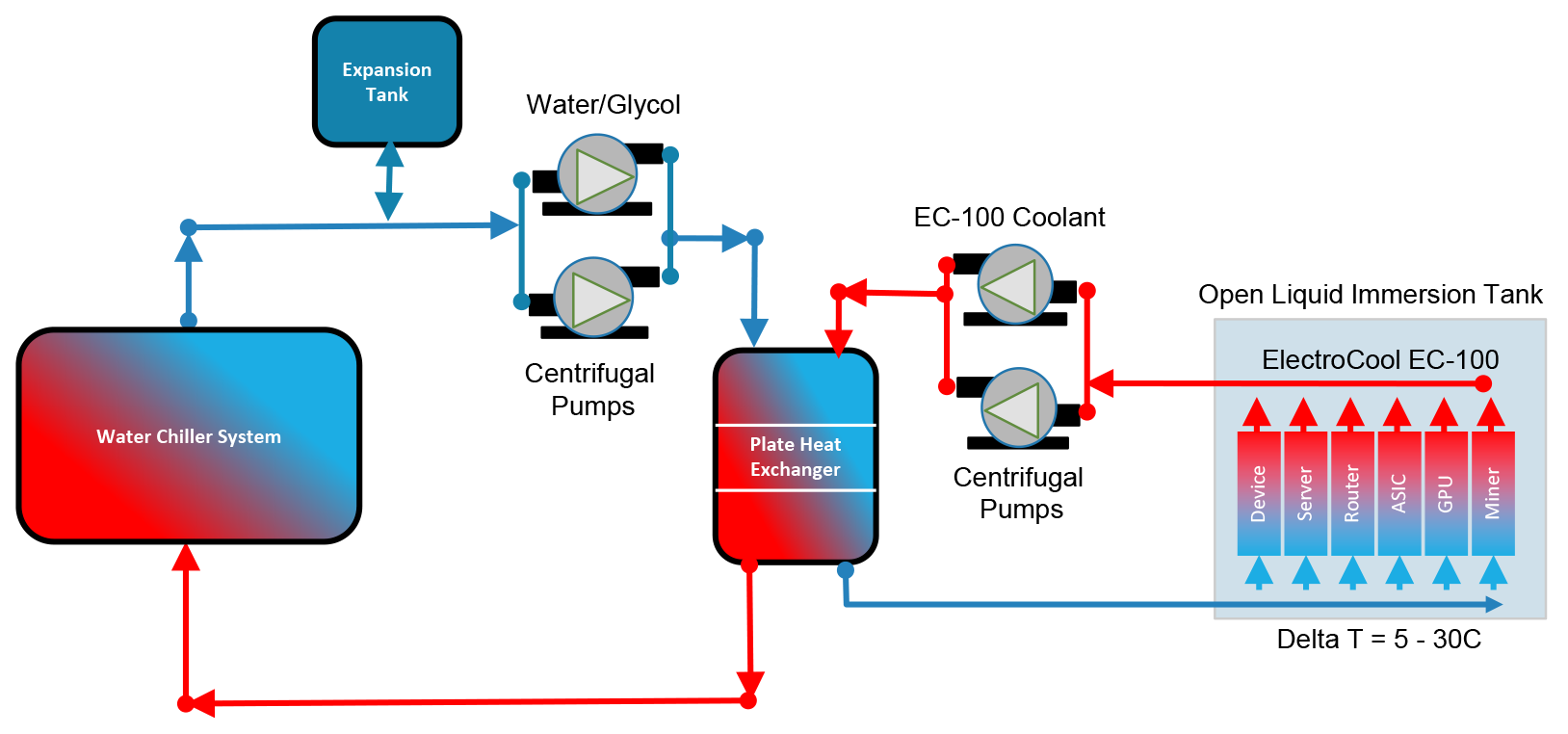
Double Loop SLIC with Water Chiller
- In this configuration there are two loops.
- One is a coolant loop from the tank to the plate heat exchanger.
- And one water/glycol mix loop from the heat exchanger to the water chiller system.
- This configuration is used where there is availability of chilled water systems in a building or installed as part of the plant.
Double Loop SLIC with Cooling Tower
- In this configuration there are two loops.
- One is a coolant loop from the tank to the plate heat exchanger.
- And one water/glycol mix loop from the heat exchanger to the Cooling Tower
- This configuration requires a source of make up water to replace the water lost to evaporation during operation of the tower.
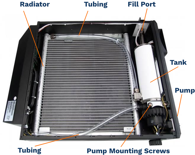
Upgrading a Koolance ERM-3K3UA
The Koolance ERMs are a great tool for use in the Lab or for small installations, this how to shows you what components you need to replace to use them with Engineered Fluids Dielectric Coolants.
Koolance ERM-3K3UA – Single Unit Dry Cooler
- www.koolance.com makes small integrated dry coolers and radiator systems for use with water-cooled PCs for the gaming industry. We often use their CDUs and some of their flow components for testing and demonstration systems. Because their products are designed for use with water, they have EPDM or Buna gaskets which are not compatible with dielectric coolants.
- The ERM-3K3UA is a small dry cooler unit with an integrated radiator, fans, pump, and tank all in a single package. It retails for about $1040.00
- The rated capacity is 2,700W with water, but our measurements indicate it can only support about 2,000W when used with BitCool due to its viscosity.
- Before using the ERM-3K3UA with Engineered Fluids Dielectric Coolants two hoses and two O-rings must be upgraded to ensure compatibility.
- Note that when you open the case of ERM-3K3UA to replace these components and use BitCool as your coolant it will void the manufactures warranty.
Koolance ERM-3K3UA Upgrade Components
Step 1: Remove the 12 screws from the top cover.
Step 2: Disconnect fan leads and remove cover, place aside.
Step 3: Entirely remove the vinyl input and output tubing by opening the hose clamps on both sides.
Step 4: Remove the 2 screws on the sides of the front cover and the 4 screws on bottom of the front cover.
Step 5: Remove the front face panel, watch out for the wires connected to the control panel on the front right side, as they are short, and the connector is hard to reconnect.
Step 6: Remove the pump by removing the 4 mounting screws
Step 7: Open the pump by turning the large diameter circular cap and replace the pump O-ring with PN: 5267T193 0.137” Thick x 2.43” OD (Dash 227)
Step 8: Replace the front cover and all screws.
Step 9: Replace hoses with PN: 5549K39 / AEM02038, Versilon 1/2″ I.D. x 3/4″ O.D. x 1/8″ Wall (C-210-A)
Step 10: Replace top cover on unit and all screws
Step 11: Replace fill port O-ring with PN: 5267T25, 0.068” Thick x 0.618” OD (Dash 014)
Clicking on the above links brings you to www.McMaster.com
Notes: the radiator is on the return / hot side of the circuit.
Fan Deletion Circuit
This clever solution came to us courtesy of Chase Blackmon – Thank you Chase for sharing!
Fan deletion is probably the most common problem we hear about when moving to SLIC systems.
Here is a simple solution that uses an adjustable frequency square wave generator that sends the sense signal to the S9 controller board spoofing it to thinking you have a fan attached and spinning at the right RPM.
Chip: ICStation 2 Channel PWM Pulse Adjustable Frequency Square Wave Digital Display Signal Generator Module
Cost: About $3.00
Find the IC Station Product Here on their website or you can also buy the IC Station Product on Amazon Here
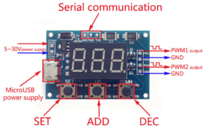
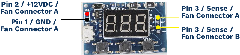
ICStation 2 Channel PWM Pulse Generator
Product Overview
- Operating Voltage: 5-30V; support micro USB 5.0V power supply
- Frequency Range: 1Hz-150KHz
- Frequency Precision: 2%
- Signal Load Capacity: 8-30mA
- Output Range: 5V
- Ambient Temperature; -30~70 Celsius
Features
- Two independent PWM generators can set the frequency, duty cycle
- The wide frequency range, high accuracy
- Support serial communication
Applications
- As square wave signal generator which generates a square wave signal
- To provide a signal to the stepping motor driver
- Adjustable pulse generation for chip use
- Produce variable pulse signal, the control-related circuit (PWM dimming, speed)
Module Description
- Frequency is divided into three ranges:
- 1.XXX (no decimal point) the smallest unit is 1Hz,the range 1Hz-999Hz
- 2.XX.X (decimal point in ten): The minimum unit is 0.1Khz; the range of 0.1KHz-99.9KHz
- 3.X.X.X (Three decimal points): smallest unit is 1Khz; the range 1KHz-150KHz)
Frequency Display Example
- “100” indicates that the PWM output pulse of 100Hz
- “54.1” indicates that the PWM output pulse of 54.1KHz
- “1.2.4.” Indicates that the PWM pulse output 124KHz
- Duty Cycle in the range: 0 to 100
- Three frequencies duty cycle is the same, all the parameters non-volatile
Serial Port Control:
- Baud rate:9600 bps
- Data bits:8
- Stop bits:1
- Parity bit: none
- Flow control: none
- Set The PWM Frequency
- 1) “S1FXXXT”: setting PWM1 frequency of XXX HZ (001 ~ 999)
- 2) “S1FXX.XT”: set the frequency of PWM1 XX.X KHZ (00.1 ~ 99.9)
- 3) “S1F:X.X.X.T”: setting PWM1 frequency of XXX KHZ (0.0.1 ~ 1.5.0..)
- 4) ‘S1’: PWM1
- 5) ‘S2’: PWM2
- 6) ‘F’: Frequency
- 7) ‘D’: Duty Cycle
- 8) ‘T’ is the end flag
Set the PWM Duty Cycle
- 1) “S1DXXXT”: setting PWM1 duty cycle XXX;(001-100)
- 2) “S2DXXXT”: set PWM2 duty cycle XXX;(001-100)
- 3) Setting Successful Return: DOWN
- 4) Setting Failback: FALL
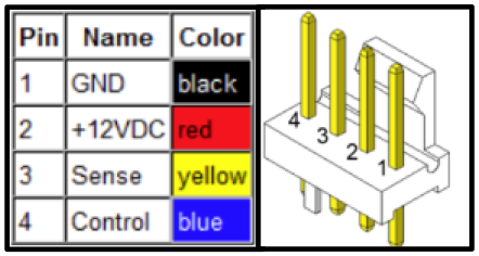
Old and New Controller Boards: Antminer S9
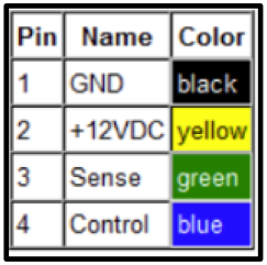
AntMiner S9 Fan Pin Out
Controller Board Version 1
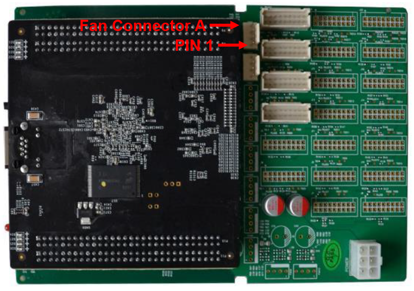
Controller Board Version 2
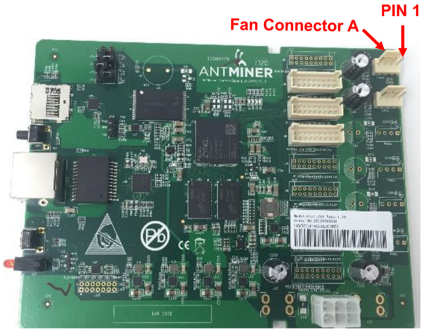
Fan Connectors: Ver. 3 Controller Board
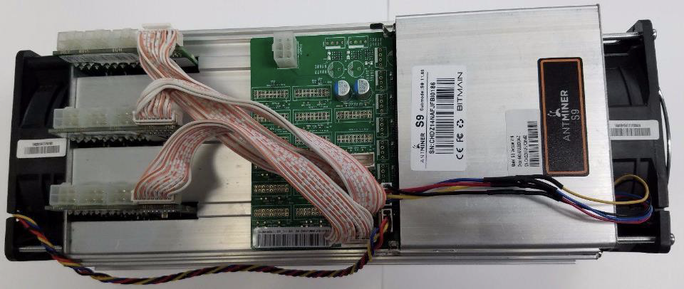
Wiring up the PWM Pulse Generator
- Disconnect and remove both fans.
- Wire the Black and Red (Pins 1 & 2) of Fan Connector A to the PWM-PG’s VIN+ and VIN-
- Wire PWM-PG’s PW1 to Pin 3 of Fan Connector A
- Wire PWM-PG’s PW2 to Pin 3 of Fan Connector B
- You do not need to wire up Pin 4 as this controls the fan’s speed and is no longer necessary
- Set the Frequency on the PWM to 30kHz for a signal rate of 6K RPM
AntMiner S9 Fan Pin Out
AntMiner S9 Fan Pin Out
Dry Cooler
A dry cooler is an air-cooled radiator unit, that utilizes a liquid heat transfer solution, such as water, Ethylene Glycol/Water, or Propylene Glycol/Water, or ElectroCool Dielectric Coolant to transfer heat in lieu of refrigerant and compressors. The coolant absorbs heat from miners in the tank and transfers it outside to the dry cooler. Depending on the climate the dry cooler may operate entirely passively through convention due to the heating of the air pocket within the dry cooler. When the temperature of the coolant is not being offloaded to the environment fastest enough dry coolers will switch on a series of condensing fans to perform its cooling. A significant benefit of this type of system is that no liquid evaporation takes place, which eliminates the need for make-up coolant. Dry coolers can often reject larger amounts of heat in a much smaller footprint than traditional direct expansion air cooled condensing units, which can be a benefit for projects with limited ground or roof space.
Pros
- Easy to size to any heat load by adding more modules in series
- Simple to operate uses convection or fans
- Lowest operating cost of all heat rejection
- When properly sized for the climate, the fans on a dry cooler should only be operated for no more than 15-20% of the time and only during the hottest times of day.
- Very low maintenance – clean the coils and maintain fans.
Cons
- Can require a lot of space depending on size.
- If placed on a roof, it may require a two loop system to prevent the fluid from draining into the tank.
Water Chiller
A water chiller is a machine that removes heat from a liquid via a vapor-compression or absorption refrigeration cycle. This liquid (typically water) can then be circulated through a heat exchanger to cool equipment. As a necessary by product, refrigeration creates waste heat that must be exhausted to ambience, or for greater efficiency, recovered for heating purposes. Water chillers can be water-cooled, air-cooled, or evaporatively cooled.
Pros
- Very low temperature water source for high density cooling
- Can be scaled to a precise service size
Cons
- Units suitable for mining are very expensive.
- It require a lot of space depending on size.
- If placed on a roof, it may require specific roof loading requirements.
- Expensive to run as they have only one speed on or off.
- Expensive to buy and to operate.
- Expensive to maintain.
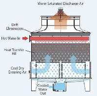
Cooling Tower
A cooling tower is a passive heat rejection device. The heated water coming from the heat exchanger is brought to the cooling tower through pipes. The water is then sprayed through nozzles onto banks of material called “fill,” which slows the flow of water through the cooling tower, and exposes as much water surface area as possible for maximum air-water contact. As the water flows through the cooling tower, it is exposed to air, which is being pulled through the tower by the electric motor-driven fan at the top of the tower. When the water and air meet, a small amount of water is evaporated, creating a cooling action. The cooled water is then pumped back to the heat exchanger where it absorbs heat.
Pros
- Very efficient at providing a source of chilled water.
- Can be scaled to a precise service size
- Relatively inexpensive to operate
- Medium complexity to maintain
- Medium cost relative to dry coolers and water chillers.
Cons
- Takes up a lot of space and generally cannot be put on a roof.
- Requires a source of available water to make up for evaporated water during cooling.
- Noisy in operation due to fans and dripping water.
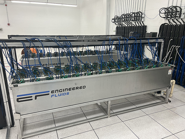
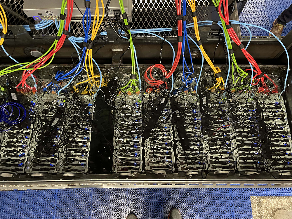
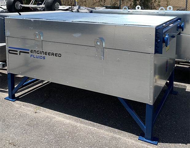
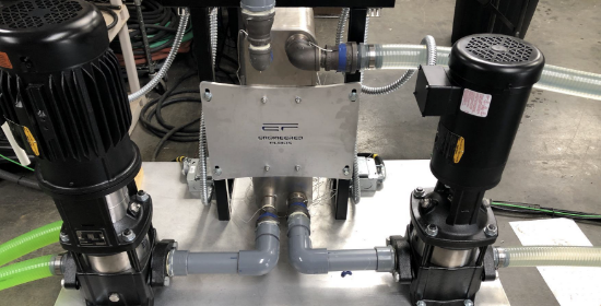
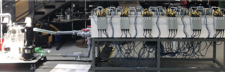
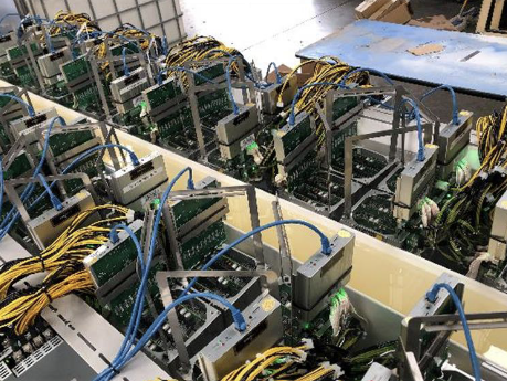
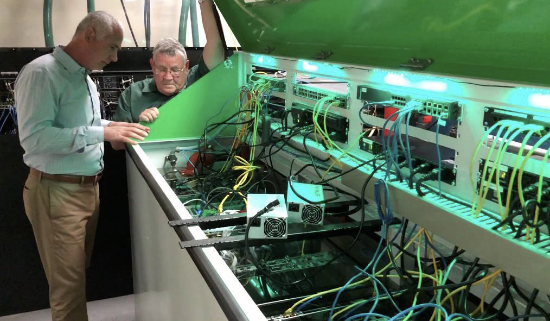
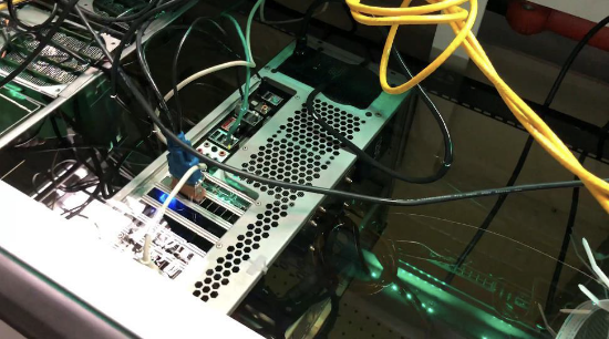
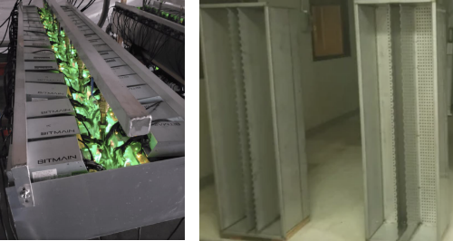
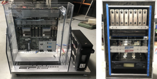
SLIC System Example Photos
Engineered Fluids’ SLICTank-2540
48 S9 Miners overclocked to 140% with a PUE=1.015
Dual Loop System with Heat Exchanger
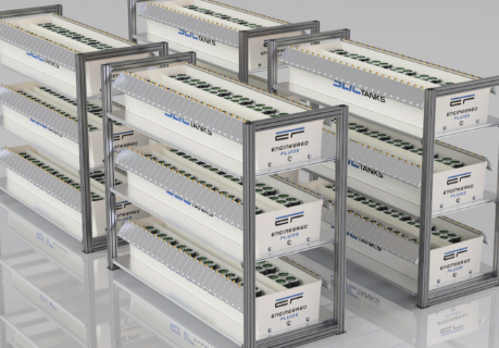
Engineered Fluids’ SLICTanks – BitCool BC-888
Midas Green Technologies – EC-100
Servers and Bit Miners in ElectroCool
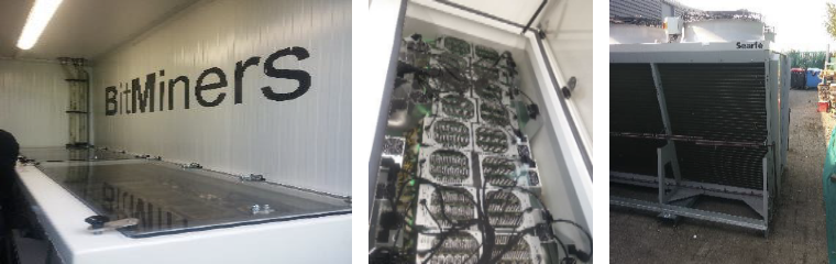
ImmersionSystems.IO – BitCool BC-888
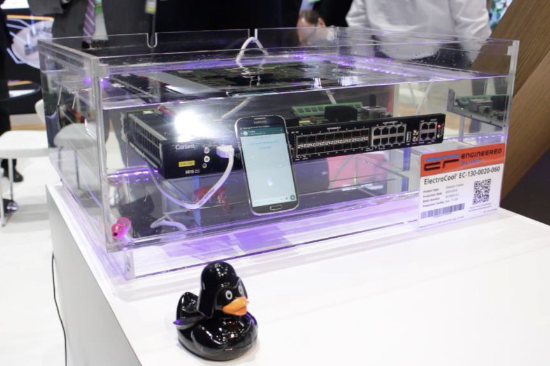
Engineered Fluids – Test Systems – EC-130
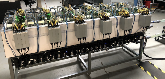
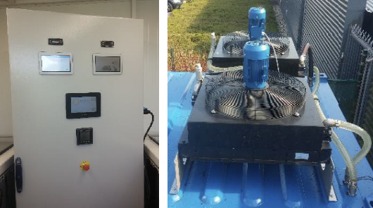
Outdoor SLIC Pod – 16x 1000W Servers
5MW SLIC – 1kW 4x Node Intel Servers
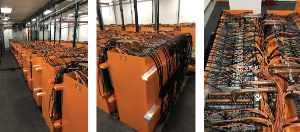
Container Based Mining Operation
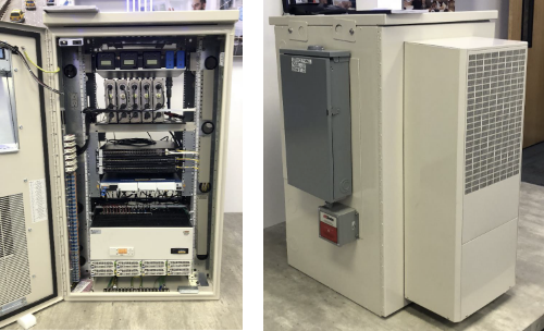
Coriant Optical Router in ElectroCool
SLIC Videos: Engineered Fluids Channel
Engineered Fluids Vimeo
You can also visit our Vimeo Video Channel to see:
- Live Demonstrations of our products
- Discussions with live customers Q&A
- Explanations of use cases
- Customer feedback on our products
You can also subscribe to our channel to get notified when we post new materials!
Engineered Fluids YouTube
You can also visit our YouTube Video Channel to see:
- Live Demonstrations of our products
- Discussions with live customers Q&A
- Explanations of use cases
- Customer feedback on our products
You can also subscribe to our channel to get notified when we post new materials!